Millimeter-scale laser steering

This tool builds on the lessons learned in the development and deployment of the centimeter-scale tool. Its miniaturization, using the centimeter-scale device as a reference point, is enabled by: (1) the use of smaller off-the-shelf optical components and some custom machined parts; (2) parallelized packaging that uses space more efficiently, which makes the device significantly shorter; (3) the use of a fixed mirror, which allows the two controllable mirrors to be placed more closely together.
An important contribution of this work is the development of a new modular design approach that allows the device to be easily assembled and disassembled, which allows for rapid testing, debugging, and development. This approach uses rigid stainless steel rails as assembly guides for the optical and mechanical components, which are placed on disks that slide onto the rails. Secondary contributions include several advancements in device control: transmission mechanics that enhance device repeatability; hysteresis compensation that improves open-loop trajectory control; and s-profiling of control inputs to improve the smoothness of response.
This work demonstrates a significant leap in the capability of microrobotic laser steering tools. It is small enough to be integrated with existing flexible surgical scopes and deployed on laparoscopic tools. The modular design and fabrication approach developed for this device are translate-able to other devices and will enable the fabrication of new, complex millimeter-sized microrobotic and medical devices.
Principle of operation: Individual components are highlighted and their contribution to overall device function described. The relationship between input control voltage and output laser position is shown:
Device assembly: Assembly is straightforward due to the modular design and fabrication approach. This video shows zoomed-in detail of the entire assembly process:
Performance demonstrations: This video shows device performance in a variety of contexts – trajectory following, dynamic control, and multi-modal control:
Colonoscope interfacing simulation: This video shows the interfacing with a commercial colonoscope and a simulated insertion with polyp resection:
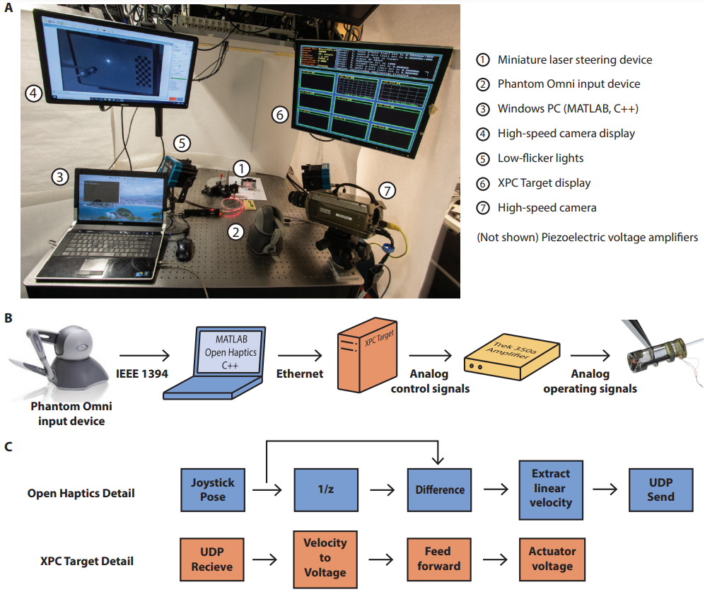
Experimental setup and system architecture: (A) depicts the measurement setup for collecting laser spot position with high-speed camera, low-flicker lighting, and supporting equipment. (B) shows the hardware architecture and signal flow for laser teleoperation from the joystick input device to the laser steering tool. **(C) summarizes the program flow for mapping joystick pose to actuator inputs within the Open Haptics API and XPC Target.

Simulink model: This is an example of a Simulink model used to control the position of the laser, in this case, via teleoperation. Desired velocities are received over UDP, integrated, then converted to voltage output commands. Additional subsystems allow for safe, repeatable startup as well as following along registered trajectories:

